
| Main Page |
|
Capacitance |
|
Polarization | Cursos |
| |
Neil C. Bruce | |||||
|
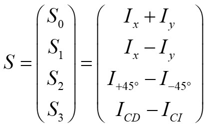
Stokes
polarimeter
The state of polarization of a beam
is described by the measurable 4-element Stokes vector of the beam.
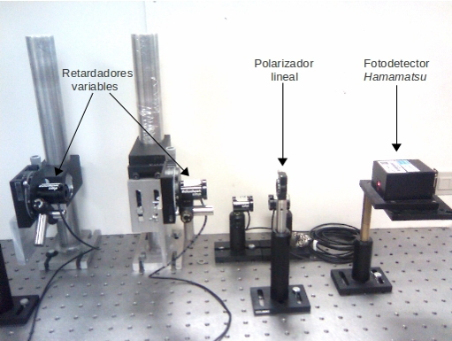
Stokes polarimeter, with the two variable retarders
on the left, the polarizer in the centre and the
detector on the right.
Now, there will always be errors and noise in any measurements, and, with 6 measured intensities, there are only 2 measured terms for each Stokes vector element, whereas with 4 measured intensities there are Stokes vector terms which require 3 measured terms, so in this case the errors and noise will accumulate more: the method with 4 measurements will give a less precise result. Mathematically, this depends on the characteristic matrix of the measuring process. The characteristic matrix of the polarimeter is constructed by writing the 4 or 6 (from the examples above) Stokes vectors of the detected light in each intensity measurement as a column of a matrix. Examples of characteristic matrices are given below:
| Combination of Detected
Polarizations |
Characteristic Matrix |
Condition Number |
| H, V, +45°, R |  |
3.2255 |
| H, V, +45°, -45°, R, L |  |
1.7321 = √3 |
| ?, ?, ?, ? |  |
1.7321 = √3 |
As can be seen, to measure the 4 Stokes parameters, the minimum condition number (an optimized polarimeter), is 1.7321 = √3. The third combination of only 4 intensity measurements has values which give an optimized polarimeter, that is, the noise in the measurements has the smallest effect on the final Stokes vector values.
Even with an optimized design, there will
always be errors in the experimental system and noise in the intensity
measurements, which mean that the measured Stokes vector will have
errors. An example is shown below, for a rotating half-wave plate
(right) and a rotating quarter-wave plate (left).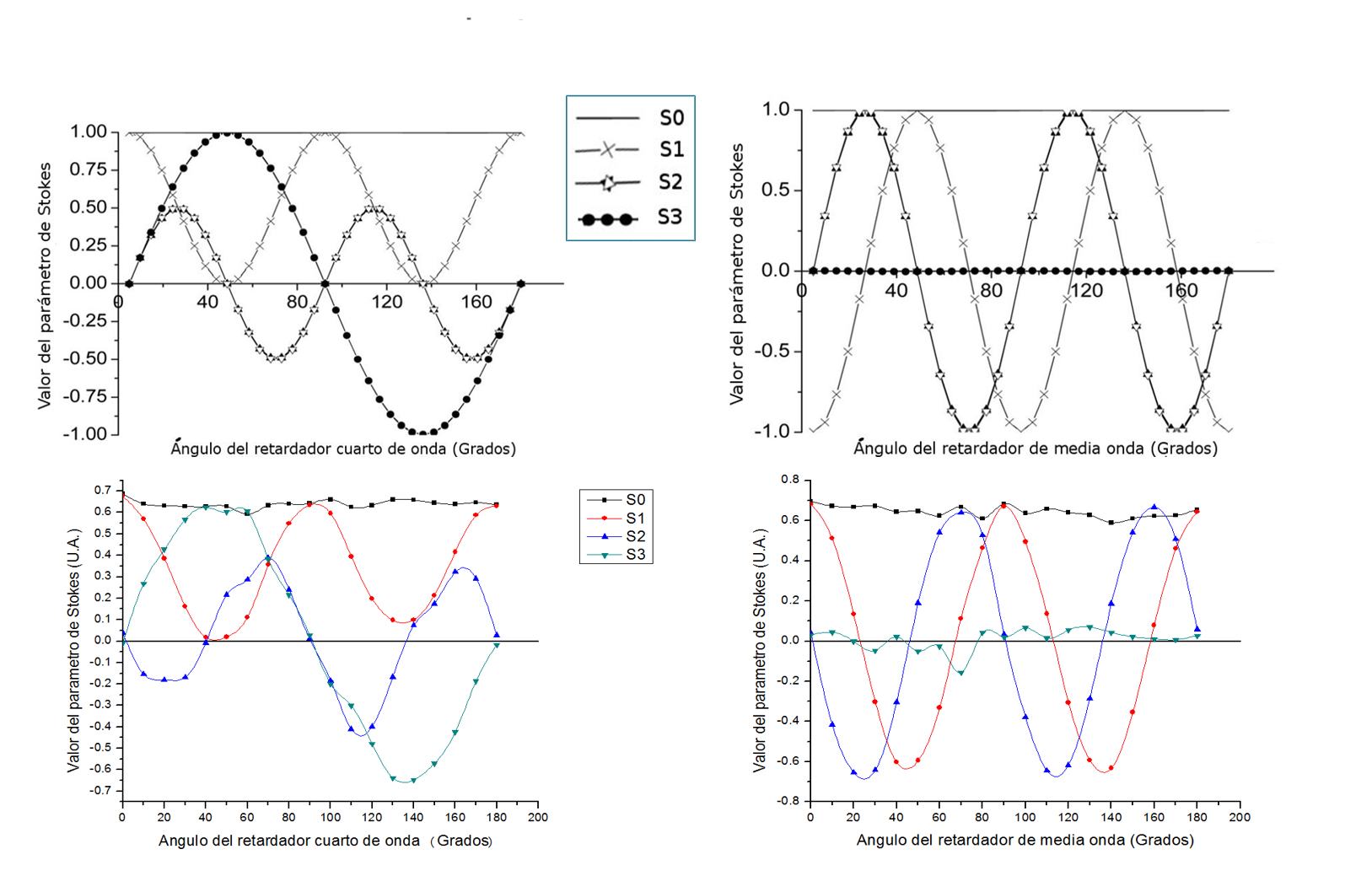
Theoretical calculations (top) and experimental measurements (bottom) of the Stokes vector parameters for a rotating quarter-wave plate (left)
and a rotating half-wave plate (right)
We are currently working on calibration methods to correct the errors which can be seen in the experimental measurements (coloured curves) in the above figure.
Publications on characterization of liquid-crystal variable retarders and Stokes polarimetry:
| ICAT |